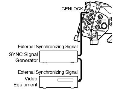
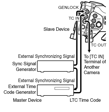
Genlock Wiring Diagram
Gy Hm890 Series Gy Hm850 Series Mobile User Guide Jvc
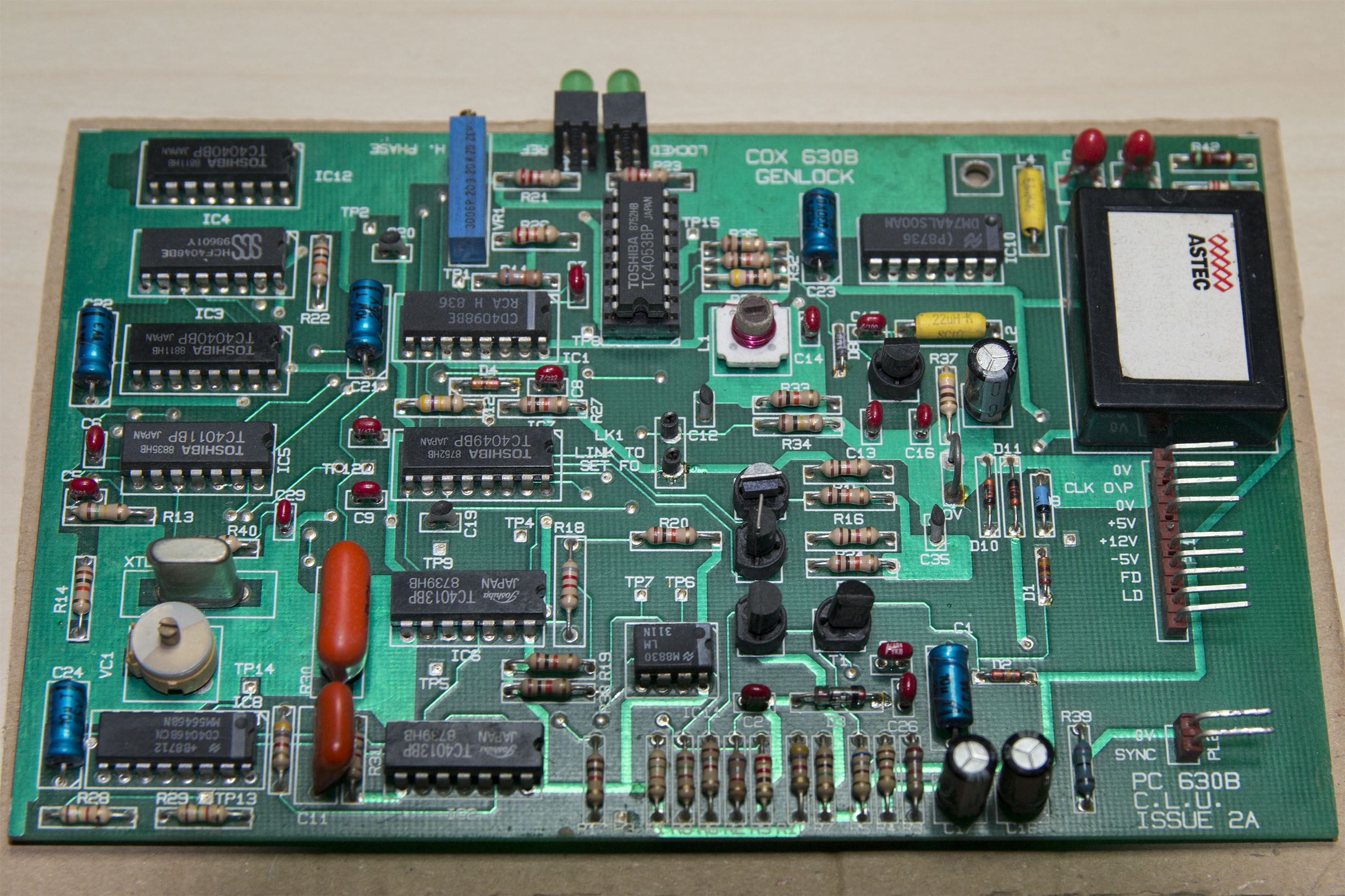
Cox 630b Genlock Board Domesday86 Com
Gy Hm890 Series Gy Hm850 Series Mobile User Guide Jvc

Communication Ports

Ru66644u1 Multi Channel Input Output And Processing Hd Sd Sdi
Http Www Nbtv Wyenet Co Uk Epromgenerator A5 Pdf
Truncated part number 2.
Genlock wiring diagram. Genlock circuit but that does not help much when trying to feed the same video output to more than one network channel at the same time. It is also possible to integrate a mini din 3 in the design to send the sync signal to the shutter glasses. In short we may change the motors operation and control by doing some modification in the above simple electrical interlocking control circuit diagram. The genlock accessory box allows you to capture frame synchronized videos where the camera are separated by more than 25 feet.
This is a simple solution that does not require any skill other than thread solding. L suffix designates rohs compliant package. Yyww is the last two digits of the year and week that the part was assembled. Block diagram video genlock pll phase detector vco circuit block ideal for genlock system reference clock range 25 khz to 1 mhz for full output clock range input clocks down to 12 khz possible with restricted output conditions see table 1 output clock range 1 25 to 75mhz on chip loop filter single 5 volt power supply.
Here is the wiring diagram of this cable. In general you need one genlock accessory box per camera unless you are routing the cabling through wiring closets then you may need additional powered genlock accessory boxs in each wiring closet. For example if we need that motor 1 should stop when motor 3 starts to run then we may use a normally close nc link of m3 in line 1. The network is a modified parallel cable paracable with one master and 5 slaves.
Cm008 Remote Camera Controller User Manual Installation And
Https Gvcms Grassvalley Com Docs Manuals Purple Copperhead G2 Copperhead G2 Manual Pdf
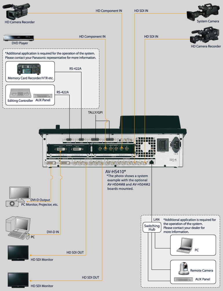
Av Hs410 Switchers Mixers Broadcast And Professional Av
Https Cn Evertz Com Resources Manuals Id 60

Pin On Tech Terms
Https Download Tek Com Manual 077023004web Pdf

Complete 3 Genlock Camera Live Rig For 375 Muff Wiggler
Http Www Broadcastrental Com Wp Content Uploads 2015 09 Xt3 Configman 14 00 Pdf
