Spdt Intermatic T106m Wiring Diagram

How To Wire T106 Timer

Spdt Intermatic T106m Wiring Diagram Wiring Diagram

Ra 8081 Intermatic Photocell Wiring Diagram With Timer Schematic

How To Wire T106 Timer

Sg 4090 Motion Light Wiring Diagram On Intermatic Low Voltage

Intermatic T100 Series Timers With Parts Manuals And Wiring
The timer shall be.
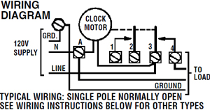
Spdt intermatic t106m wiring diagram. These dependable time switches can handle electrical loads up to 40 a per pole and allow for up to 12 on off operations per day. Line 2 if present is. To wire as single pole double throw install jumper the same gauge as line wire between 2 and 3 and connect line to 2 loads to 1 and 4. Wire size max 8 awg.
It shows the components of the circuit as simplified shapes as well as the power as well as signal links in between the devices. The t100 series mechanical time switch has proven it can stand the test of time. The timer field wiring connections shall be secured by means of a teeter type terminal screw to provide secure connections for appropriate wire sizes. Intermatic t106m timer 120 277v spdt 24 hour dial mechanical timer mechanism intermatic t104 electromechanical timer 208 277 v 40 a 1 23 hr 1 12 cycles per day gray intermatic t104r 208 277 volt dpst 24 hour mechanical time switch with outdoor case.
The timer shall shall not have a hold feature and shall have a time cycle of see time cycles listed. The timer shall be spst dpst spdt. Tungsten range s 40 a 120 240 vac 60 hz. Variety of intermatic 240v timer wiring diagram.
To wire as single pole normally closed move clock motor lead from terminal 3 to 1 and connect line to 1 load to 2. To wire switch follow diagram above. A wiring diagram is a simplified traditional pictorial representation of an electrical circuit.

Intermatic Timer T103 Indoor 24 Hour Dial 120v 40 Amp 2 Poles Timer

Intermatic Timer T104p 24 Hour Dial 208v 277v 40 Amp 2 Poles Timer

How To Wire Intermatic T10604r

Intermatic Timer T102p 24 Hour Dial 208v 277v 40 Amp 1 Pole Timer
Intermatic Timer T105 Indoor 24 Hour Dial 120v 40 Amp 1 Pole

Photos Of Wh40 Timer
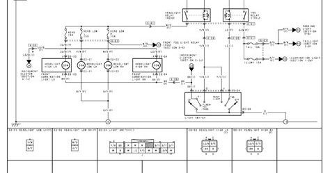
75 Series Landcruiser Headlight Wiring Diagram Wiring Diagram

Control Pump Or Timer With Rain Sensor Http Waterheatertimer
1dde472 Agway Lawn Mower Wiring Diagram Wiring Library

2008 Sprinter License Plate Light Wiring Diagram Wiring Diagram

Index Of Images

Add Rain Sensor To T8845pv Sprinkler Timer Http
Https Www Intermatic Com Media Inriver 7262 8743 Ashx T30604r Instructionmanual En
